


QJ-L QJ-T型起重机立式减速器
QJ-L QJ-T Crane Vertical Decelerators
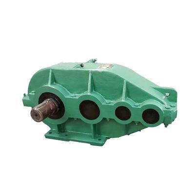
一、概述Brief
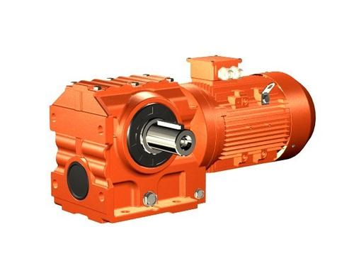
起重机立式减速器部分分为QJ-L,QJ-T两个系列,主要用于起重机运行机构,也可用于运输.冶金,矿山、化工、轻工等各种机械设备的运行机构中。齿轮.齿轮轴采用中碳合金钢中硬齿面,具有结构紧凑、承载能力较高等优点,是我厂继Zsc型、ZSC(A)型减速器之后推出的又一代新产品。
The Crane verticl decelerators has two series,type QJ-L and type QJT. They are the operating mechanism of crane and other machinery in transportation, metallurgy, mining, chemical industry and light industry. The gear and axle are made of middl carben alloy steel and middle carbide-faced, which are fastened structure with high carrying capacity. Such kind of reducers are our updated decelerators after ZSC and ZSC(A) reducers.
二、QJ-L型减速器外形、尺寸及装配型式
Outlook, assembling size and installing form of QJ-L reducer


四、QJ-L, QJ-T型减速器承载能力表
Allowed power and output torque of QJ-L, QJ-T reducer

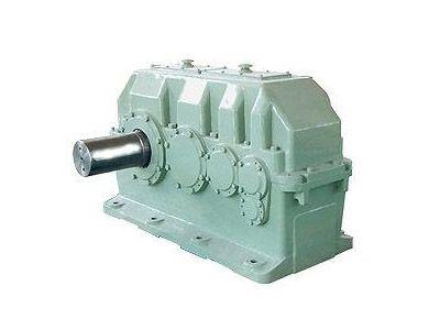
QJG-L型起重机立式减速器QJG-L type reducers
根据******标准JB/T8905.3-1999生产QJG-L型减速器主要用于起重机的小车运行机构和部位让式起重机、装卸桥等大车运行机构中,也可用于其它需要立式安装的设备传动。
Whichare produced on basis of JB/T8905.3-1 999,are mainly applied in craning,parts craning and Loading-unloading bridge.Also they can be applied in other vertical installing machines.
特点Property:
1.QJG-L型减速器采用铸铁箱体,底座式侧面安装立式减速器;
2.三级传动,速比为16-100;
3.该系列有7种规格,名义中心距为140-400mm;
4.小规格减速器为油浴式润滑,280以上的减速器采用集中喷油润滑。
其它特点同QJ型减速器。
1.Casting iron box is applied in QJG-L type decelerator and at side of pedestal the vertical decelerator is installed;
2.Three stage transmission with speed ratio of 16-100;
3.Seven rinds of specs for QJG-Lseries and nominal center space of 140-400mm;
4.Qil bathing lubrication for small size machines and central oil spuring lubrication for machines over 280.
型式Type
1.结构型式:QJG-L型减速器为三级立式带底座减速器。
2.装配型式,QJG-L 型减速器共有六种装配形式,见图
1.Structure type:three stage vertical reducers with pedestal.
2.Installing type:There are six installing types for QJG-L type reducers which are showed below,

外形及安装尺寸Outlook and nstalling size
QJG-L型减速器的外形及安装尺寸见图和表
The outlook and installing size of QJG-L type decelerator are shown in graph and chart below.

承载能力Carrying Capacity
QJG-L型减速器当工作级别为M5时的输出转矩和高速轴的许用功率见表
stage of M5please check table below.
QJG-L型减速器的输出转矩和高速轴许用功率(工作级别为M5)
Output torque and high-speed shaft allowed power of QJG-L type decelerator(working stage of M5)

QJG-L型减速器为连续工作时的输出转矩和高速轴的许用功率(见下页)
Output torque and high-speed shaft allowed power for continuous QJG-L type decelerator
减速器输出轴端的瞬时允许转矩为额定转矩的2.7倍。
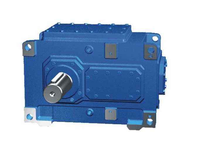
QJG-T型起重机套装式减速器
QJG-T型减速器是QJG-L型减速器的基础上派生的,主要用于起重机的运行机构,也可用于其它机械需要立式套装的传动中,用以代ZSC(A)型减速器
The temperary allowed torque of output shaft edge is 2.7 tines of rated torque.
QJG-T craning decelerator
QJG-T craning decelerator,derived fron QJG-L type decelerator,is mainly used in Craning and other machines with vertical set-installing operation to replace ZSC(A) type reducer.
特点: Property
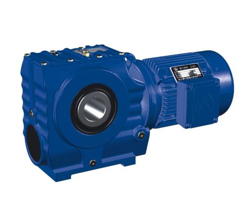
QJG-T型减速器的输出端为圆锥套,减速器就套在主机的被动轴上,将其端部固定,减速器的重量也支承在该轴上。在箱体上部设有装孔,通过销轴固定在支架上。
With cypinder output edge,the QJG-L reducer is installed on passive shaft.The weight is there after sustained. the upper of case locates some holes to fastened onto shelf with screw shaft.

箱体分三部分,部分成“⊥”形,作立式减速器使用,下箱体油不易渗漏,输出轴中心线到下端极限位置尺寸比较小。其它特点同QJG-L型减速器.
The case is made up by three parts and some are shaed as vertical decelerator.The size between center line of output shaft and end position is rather small.other properties are the same as that of QJG-L reducers.
型式Type
1.装配型式QJG-T型减速器的装配型式有四种,见图
2.轴端型式高速轴采用圆柱形轴伸,平键联接,低速轴采用空心轴套,锥形轴孔,平键联接。
1.Installing type: There are four types for QJG-L type decelerator showed below,
2.Shaft edge type :Cylinder extension for high-speed shaft and shaft connection.
型号标记示例Symboi example
起重机套装式减速器,名义中心距a,=200,公称传动比i=40,装配型式第1I种,标记为:减速QJG-T200-40-川I
Craning redueer,nominal center space a, =200,nominal transmission ratio i=40,instaling form is ll ,the sumbol is :reducer QJG-T200-40- I..
主要技术参数Main tech data
QJG-T型减速器的中心距和传动比与QJG-L型减速器相同。
Center space and transmission ratio of QJG-T reducer are the same as those of QJG-L reducers.

外形及安装尺寸Contour and intalling size
QJG一T型减速器的外形及安装尺寸见表2-15和表2-20。
The contour and installing size of QJG-T type decelerator are shown in table 2-15 and 2-20. Loading capacity
承载能力Loading capacity
QJG一T型减速器的输出转矩和高速轴的许用功率与QJG一L型减速器相同.见表2-18QJG和表
The output torque and high-speed shaft allowed power of QJG-Tdecelerator and QJG-L decelerator .the related values art listed in table 2-18 QJG
选择方法Selection method
选择原则Selection principle
1)在选择减速器时,首先要满足工作条件。即高转速,***大齿轮圆周速度,环境温度和转向等。
2)满足机械强度的要求,如输入轴的功率(或输出轴的转矩) .轴伸的***大径向力和瞬时***大转矩等。对于连续使用的减速器还要满足热功率。
3)满足转速要求.根据原动机的转速和工作机械的要求转速选择***接近的传动比(***好是减速器的实际传动比,如果末给实际传动比用公称传动代替).一般两者极限偏差2级为土4%.3级为土5%。如果特殊要求,我公司联系特殊配制。
4)根据主机要求减速器的安装位置.界限尺寸。联接部位、传动性能的要求.确定减速器的结构形式,安装型式和装配形式。
5)根据输入和输出的联接方式,选择轴端型式。
6)考虑使用维修方便,选择注油口,排油口的位置,润滑方式。散热等。
1) the operating condition must be qualified when select decelerator.for example,the high speed rotation,max gear circle velocity,ambient temperature and rotation.

2) To meet mechanical intensity .for example,the input shaft power (or output shaft torque),.max radial force of shaft extension and intermittent max torque Aslo the heat power of continuous decelerator.
3) To meet rotationg speed .the most favorable transmission ratio should be selected according to the given rotating speed and required rotating speed (the actual transmission ratio,if not that,nominal transmission ration is favorable ).Usually the defference bettween them is 4%for 2 stage,5%for 3 stage.If there' s any special requirement,please contact us.
4)To determine structure mode, installing form and assembling type according to in stalling position,margin sizc.connecting place and driving property of decelerator.
5) To select connecting mode of input and output,to select shaft edge type.
6) To select oil inlet and outlet position ,lubricating mode and radiating.
选择计算Selecting calculation
1)QJ型(包括QJ一D/QJG-T,QJ-L)以及ZQA型减速器,用于起重机各机构时,根据GB3811《起重机设计规范》(以下简《规范》的规定,起重机机构的工作级别分为M1-M8八种.本手册所列的承载能力为M5工作级别,要用在其它工作级别时应按公式进行折算
式中
PMS=PMS x 1.12(1-5)KW
PMS-减速器承载能力表中的高速轴许用功率值(KW);
PMI-相对Mi工作级别的功率值(KW)
i一工作级别数1-8
2)起重机各机构疲劳计算的基本载荷 Mmax
a)起升和非平衡变幅机构
1) when QJ decelerator (including QJ-DJG-T,QJ-L type )and ZQA decelerator are applied in craning equipments,according to GB381 1<design stipulation of craning > ,there are eight working series M1-M8, the enclised loading capacity is M5. if other series is applied ,the followed formula is applied,
Where, PMS
一the hugg-speed sgaft akkiwed powed power in loading capacity table (Kw)
PMI一the powe of Mi series (KW)
1一 the working series 1-8
2) the basic leak load of craning MMAX
3) lofting and unbalanced structure
Mmax = φ6MN Nm φ6=1/2(1=φ2)
φ6一动载系数: φ6-load factor
Mn -电动机额定转矩(Nm) Mn=motor rated torque (Nm)
φ2- -起升载荷系数,φ2=1-2 当起升速度高,系统刚度大,操作猛时,取值较大值。
见<规范>附录B。
φ2 = liting load factor, φ2=1-2, If liting speed is high, large ragidity and heavy strike,
the larger value is preferable in <stipulation> appedix B.
b)运行和回转机构operation and back-turning mechanism
Mmax=φ5x φ6mn
式中Where
ф5一弹性振动增大系数ф5=1.5-1.7 - stretching vibrant arising factor
ф8一刚性动载系数08=1.2-2.0
一rigid loading factor
ф8与电动机的驱动特性和计算零件两侧的转动量的比值有关。见《规范》附录P。the
value of 8is related to ratio between driving vharacter and moment of inertia.please see appendix PO.
平衡变幅机构Balance changing structure
疲劳计算基本载荷取为该零件承受的等改幅静阻力矩,其它零件取为电动机额定力矩传到该计算零件力矩的1.3-1.4倍。当瞬时***大转矩低于2.7倍的额定转矩时,可以进行静强度校核,当超过此值时,应验算零件强度,或者选大机座号的减速器.
In leak calculation the basic load is determined by loaded resistance torque of the parts, for other parts,the basic load is 1.3-1.4 times of torque from motor rated torque to this related parts.You can check under silent intensyty should be checked and larger type of decelerator should be selected.
3.根据疲劳计算基本载荷和转速可算出该工作级别的功率值Pmi
3.The related power of this series can be calculated according to basic leak load and torque.
Pm=Mnx x n/9550(KW)
式中Where n一减速器输入轴转速(r/min) n-input shaft rotating speed(r/min)
如果工作级别不是M5.可安式(2-1) 换算至M 5工作级别的功率Pm5.然后再根据Pm5
输入转速n和公称传动比i选择减速器。
If the series is not M5,the series power Pmcan be calculated according to formula 2-1 ,and the decelerator can be selected on Pm,input rotating speed nand nominal transmission ration i.
选用实例Selecting example:
1)一台起重量为32t.跨度为25.5m的桥式起重机.其起升机构功率为60Kw.转速为750r/
min.起升速度为8m/min.机构的工作级别为M6.选择减速器(减速器的传动比为40,要求
第II种装配型式,齿轮轴瑞)。
1)bridge cranc with weight of 32ton and span of 25.5m,the lifting structure power is 60Kw, the rotating speed is 750r/min,the lifting speed is 8m/min,the working series in M6.the related decelerator should be selected (transmission ratio is 40,the third installing form,gear shaft edge).
电机的额定转矩Rated torque: Mn=9550p/n=9550 x 60/750=764.8 N'm
根据《规范》附录B,起升载荷分配系数φ2=1+0.71v=1+0.71 x 8/60=1.1 According
to <stipulation>B,lift load factor φ2=1+0.71v=1+0.71 x 8/6=1.1
式中where
V-起升速度(m/s) V-liting speed (m/s)
动载系数: φ6=1/2(1+φ2)=(1+1.1)=1.05 loading factor φ6=1/2(1+φ2)=(1+1.1)=1.05
疲劳计算基本载荷Mmax=φ6mn=1.05 x 764.8-803N.m
相对M6工作级别的功率M6' spower
PMB=MMAX x n/9550=8038750/9550=63Kw
折算成M5时的功率related M5power
PM5-PM5 x 1.12(6-5)=63 x 1.12=70.65Kw
查表2-8,当n=710r/min,i=40时,高速轴许用功率为78Kw,相对的减速器为:
Check table 2-8,if n=7 10r/min,i=40 the allowed high-speed shaft power is 78Kw,the related decelerator is :
QJS200-40IIC或QJS-D500-40IIC型减速器。要求三支点用前者,要求带底座的用后者。
QJS500-40 IC or QTS-500-40 II C the former is for three-point sustaining and later is
for machine with stand.
2)一台双梁门式起重机,其大车运行机构为两套,一套电动机的额定为7. 5Kw,转速
n=1000r/min,工作级别为M7 ,选择起重机套装式减速器,(传 动比为i=35.5,第II种装配型式)。
2)a double-door crane,the operating structure is two sets,of which the motor power is 7.
5Kw,the rotating speed is n=1000r/min,working series is M7, to select a craning set decelera- tor (transmission ratio of 35.5 the second installing form)
电动机的额定转矩Motor rated torque
MN=9550p/n=9550 x 7.5/1000=71.7 N.m
疲劳计算基本转矩basic leale torque
MMAX=φ5φ8 x MN
取φ8=1.5,取φ8=1.4
Mmax=1.5 x 1.4 x 71.7=150.57
相对M7工作级别的计算功率calculated power for M7series
PM7=Mmax x n/9550=150.57 x 1000/9550=15.75Kw
折算成M5时的功率related power for M5
Pm5=Pm7 x 1.12(7-5)=15.75 x 1.122=19.75Kw
查表2-18,当n= 1000r/min,i=35.5时,高速轴的许用功率PM5=21Kw,相对应的减速器为QJG-T280-3551满足要求.
Check table 2-1 8,when n=1000/r/min,i=35.5, the allowed power of high-speed shaft Pm5=21Kw,the related reducer QJG-T285-355 II can meets demands.